
16路舵机控制扩展板
功能描述:
1. 使用I2C接口,不占用GPIO接口(默认地址0x6F)
2. 同时支持树莓派(3.3v电平)和arduino(5v电平),但两种主控不能同时控制
3. 支持16路PWM通道输出,可以控制16路舵机或者LED灯
4. 12位分辨率,可调PWM频率高达1.6KHz,可配置的推挽或开漏输出
5. 3P标准接口,方便连接舵机和LED灯
6. 4位可调地址(A0-A3),方便级联扩展板,最大可级联16个扩展板(可以控制256路舵机或LED灯)
产品参数:
1.舵机部分供电范围:4.5V~5.5V的DC直流(电压与舵机的参数有关,一般使用5V DC)。
2.控制通道:同时控制16路。(舵机速度精确可调,机器人动作流畅自如)
3.通讯输入:I2C
4.信号输出:PWM(频率高达1.6KHz)
接口定义图

使用步骤:
1.使能树莓派的I2C接口,参考教程http://ukonline2000.com/?p=728
2.下载软件和参考程序
sudo apt-get install git
git clone https://github.com/geekroo/Geekroo-PiCobber-PWMServo.git
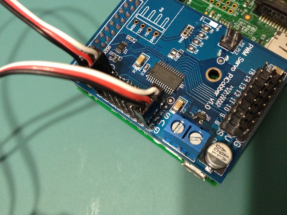
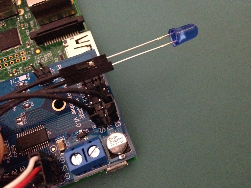
3.将舵机或者led灯连接到舵机扩展板上,如下图(请一定注意舵机的线序)
连接舵机
连接led灯
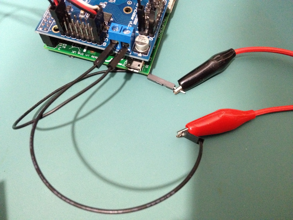
连接5V电源输入
4.运行测试程序,舵机/led灯现在应该正常工作了
cd /Geekroo-PiCobber-PWMServo
sudo python Servo_Example.py
~~~~~~~~~~~~~~~~~~~~~~~~~~~~~~~~~~~~~~
Library Reference
The driver consists of the following functions, which you can use to drive the underlying hardware when writing your own application in Python:
Initialize Object
You can create a new object for each HAT with
pwm = PWM(0x40)
In this case, pwm (lowercase) is the object created, and PWM(0x40) is the creation call. By default, all HATs are address 0x40, but by changing the address jumpers, you can create objects that use other addresses such as 0x60, 0x42, etc.
setPWMFreq(freq)
Description
This function can be used to adjust the PWM frequency, which determines how many full ‘pulses’ per second are generated by the IC. Stated differently, the frequency determines how ‘long’ each pulse is in duration from start to finish, taking into account both the high and low segments of the pulse.
Frequency is important in PWM, since setting the frequency too high with a very small duty cycle can cause problems, since the ‘rise time’ of the signal (the time it takes to go from 0V to VCC) may be longer than the time the signal is active, and the PWM output will appear smoothed out and may not even reach VCC, potentially causing a number of problems.
Arguments
- freq: A number representing the frequency in Hz, between 40 and 1000
Example
The following code will set the PWM frequency to the maximum value of 1000Hz:
1. pwm.setPWMFreq(1000)
setPWM(channel, on, off)
Description
This function sets the start (on) and end (off) of the high segment of the PWM pulse on a specific channel. You specify the ‘tick’ value between 0..4095 when the signal will turn on, and when it will turn of. Channel indicates which of the 16 PWM outputs should be updated with the new values.
Arguments
- channel: The channel that should be updated with the new values (0..15)
- on: The tick (between 0..4095) when the signal should transition from low to high
- off:the tick (between 0..4095) when the signal should transition from high to low
Example
The following example will cause channel 15 to start low, go high around 25% into the pulse (tick 1024 out of 4096), transition back to low 75% into the pulse (tick 3072), and remain low for the last 25% of the pulse:
1. pwm.setPWM(15, 1024, 3072)
If you need to calculate pulse-width in microseconds, you can do that by first figuring out how long each cycle is. That would be 1/freq where freq is the PWM frequency you set above. For 1000 Hz, that would be 1 millisecond. Then divide by 4096 to get the time per tick, eg 1 millisecond / 4096 = ~0.25 microseconds. If you want a pulse that is 10 microseconds long, divide the time by time-per-tick (10us / 0.25 us = 40) then turn on at tick 0 and turn off at tick 40.
